Monday, April 22, 2013

Duct Tape vs. Mastic

In a previous blog, we discussed the Home Energy Rating System (HERS), a number between 0 and 150 which quantifies the energy efficiency of a home.  The lower the number, the more energy efficient the home.  The target for the rehabs I've been part of in Detroit is a HERS rating of 85 or lower.
 
Image credit
 
 But even if a HERS rating meets the above standard, it does not insure that heating and cooling is properly distributed throughout the home. HERS ratings reflect the amount of energy leaking through the thermal envelop.  It does not reflect how well heating and cooling is distributed within it's envelop.
 
  
 Duct pressurization is key to providing sufficient heating and cooling to every room.  Every room is designed to receive an minimum amount of heated or cooled air per minute in order to maintain it within a comfortable temperature range.   The volume of air is measured in cubic feet per minute or cfm.  Furnaces are sized to push enough air through a home's ductwork so that each room receives its designed amount of cfm.  The level of cfm produced at the furnace reduces as it is pushed through turns and curves within a ductwork system.  Pressure losses due to these twists and turns is accounted for in furnace sizing calculations, but excessive leakage due to poor construction is not.  Minimizing duct pressure losses insures that the most remote corner of an upper floor bedroom is properly heated and cooled.
 
Energy codes address the quality of duct sealing, but many jurisdictions are just beginning to enforce them.   Energy-Star qualified homes are required to have a Duct Blaster test performed to confirm a minimum level of duct pressurization loss. 
 
But before inspections or tests are performed, builders have a choice between two methods to seal duct connections:
 
Mastic


Mastic is a gooey, non-hardening material that is spread over duct seams with a paint brush, putty knife or simply with glove covered fingers.  If gaps are greater than 1/16 or 1/8 inches wide, then a fiberglass reinforcing mesh tape should be embedded in the mastic.  To be effective, the mastic should be applied to at least a nickel thick.

In rehabs, mastic can be difficult to apply to existing ducts which tightly fit between floor joints and sheathing.  But if applied properly, mastic is the most effective duct sealing method.

Tape


Now everyone jokes about the usefulness of duct tape.  But when it comes to actually using tape for sealing duct joints and connections, not all duct tapes are created equal.  Your typical cloth-backed rubber adhesive tape fails fairly quickly when exposed to time and temperature changes. 

Most energy codes require any tape used on ducts must be labeled in accordance with UL 181A or 181B.  But since  the UL181 listing was created as a smoke and flame test, the presence of the label is no guarantee of its effectiveness as a sealant.  A tape's sealant capacity is better reflected by its base material.  Two base materials have the best sealing capabilities:  butyl and oriented polypropylene (OPP).  When searching for a duct tape, one should select UL181 labeled tapes with base materials of butyl or OPP.

As energy codes improve, the importance of duct pressurization is also increasing.  Though only Energy-Star qualified homes are currently required to have duct leakage measured, the requirement will soon be expanding to other types of housing .  Therefore, the materials and methods used by builders in making  duct connections  will play primary roles in meeting future code requirements.  But more important than the code, properly constructed connections insure the comfort and happiness of the homeowner.

----------------
Holladay, Martin, "Sealing Ducts: What's Better, Tape or Mastic?", August 6, 2010, GreenBuildingAdvisor.com.

Monday, April 8, 2013

East English Village

Between 1808 and 1810, five eastside Detroit ribbon farms were registered under the family names of Little, Rivard, Fournier and Tremble.  With Detroit's expansion east, in 1925, the farms were subdivided into residential parcels and the neighborhood of East English Village was born.  A home construction boom began in 1928, peaking in the early 1930s as homeowners rather than developers hired builders to design custom ordered homes.  This brought to life the neighborhood's distinctive character.


Today, the neighborhood is home to approximately 2,100 families, many of whose homes have only changed hands one or two times.  The area is bounded by Outer Drive to the east, Cadieux Road to the west, Harper Avenue to the north and Mack Avenue to the south. 

The Detroit Land Bank Authority's infusion of federal dollars, through a program known as the Neighborhood Stabilization Program (NSP), is rehabilitating homes within the community.  I've had the privilege of being part of more than 15 fast-tracked rehabs currently being performed by teams of contractors and rehab specialists. 

More importantly, the rehabs incorporate the latest in thermal envelop construction technology.  The goal of the program is to not only restore these historic homes, but to improve their energy efficiency.

Below is a sampling of some of the houses currently under construction:


------------------
More information can be found at East English Village's Website

Friday, March 29, 2013

Historic Boston Edison

Since summer, I've been immersed within a 36-block historic Detroit neighborhood known as Boston Edison.  It  contains approximately 900 houses bordered by Boston Boulevard on the North, Edison Avenue on the South, Woodward Avenue on the east and Linwood on the West. 


The neighborhood's early development was controlled by primarily three families: the Joy, Newberry and Voigt families.  With the majority of homes built between 1905 and 1925 some of Detroit's most prominent turn-of-the century citizens lived here: Henry Ford, James Couzens (Mayor of Detroit from 1919 to 1922 and appointed U.S. Senator), W.O. Briggs (former owner of the Detroit Tigers), Sebatian Kresge (founder of the S.S. Kresge Company) and Ty Cobb (Detroit Tigers center-fielder and Major League Baseball's all-time career batting average leader) .

Working in conjunction with the Detroit Land Bank Authority, work is finishing on four (4) homes subsidized by Federal stimulus money known as the Neighborhood Stabilization Program (NSP).  Doing a little research, I found some prominent past owners of two of the homes.

1626 Boston
Clarence W. Avery
In 1918, Avery moved to 1626 W. Boston Boulevard, living there until the early 1920s.

In 1913, Henry Ford hired Clarence Avery for a summer job. A quick learner, Avery became Charles E. Sorensen's assistant.  The two focused on developing the moving assembly line. Although the originator of this idea is uncertain, Avery certainly had the biggest hand in developing it. By timing each step to maximize the speed of production, Avery and Sorensen reduced the assembly time of the Model T from 12.5 hours to 2.7.


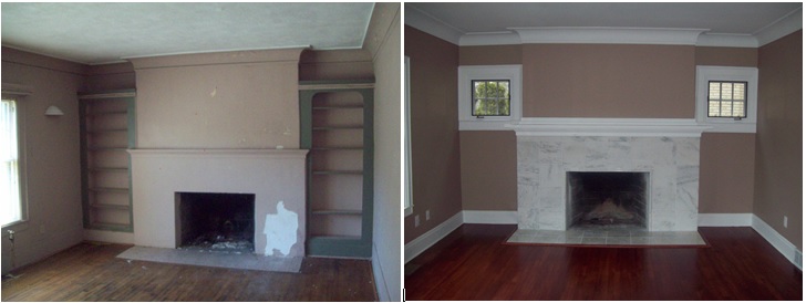
Before                                             After
Before                                               After
Before                                                      After
Before                                                     After
 
1216 Edison
Albertus Darnell
Albertus Darnell lived at 1216 Edison from the early 1910s through the late 1940s.

When Detroit Junior College was organized in 1917, Albertus Darnell became head of its Mathematics Department. In 1923, Detroit Junior College was replaced by the City College of Detroit, and Darnell was named Assistant Dean. He continued in this position until City College merged with other institutions to become Wayne (later Wayne State) University in 1934, when he was named Dean of the College of Liberal Arts. Darnell continued in this position until his retirement in 1939.


Before                                                         After
Before                                                       After
 
Before                                        After
 
------------------
For additional information go to Historic Boston Edison Association's Website

Thursday, March 14, 2013

Home Circuit Protection

There's nothing like trying to plug-in an appliance and being unable to find a grounded outlet.  Teaching myself to be a do-it-yourself electrician, I spent a Saturday replacing the two slot electrical outlets in my home with grounded three slots.  Luckily, I found the non-metallic (NM) wire (I'm trying to sound like an electrician) contained three wires.   The black wire is hot, the white is neutral and a third (either bear or sheathed in green) is the ground.   So my work was limited to connecting the new three slot grounded receptacle to the grounding wire.

Image Source
Bringing old houses up to modern electrical standards can be a challenge since it wasn't until the 1960s that electrical codes requiring grounding wires began to be enforced.  And if interior partitions aren't being stripped to their studs, fishing new wire can be challenging.  Code allows for original ungrounded wiring is to remain in place as long as protection from electrical shocks and fire is provided by Ground Fault Circuit Interrupter (GFCI) and Arc-Fault Circuit Interrupter (AFCI) outlets and/or breakers.

Everyone is probably familiar with GFCI protection.  These are the outlets and breakers with reset buttons.  You typically find the outlets in bathrooms, kitchens, laundries and exterior locations.  But now codes are beginning to require a new type of protection, AFCI.  Here's my research on what the difference is between the two and why they are both important in protecting the homeowner.

Ground Fault Circuit Interrupter (GFCI)

Image Source 
GFCIs when installed at outlets or breakers are designed to protect against electrical shock.  They measure the current passing through the black "hot" wire and returning through the white "neutral" wire.  Typically, there should be no difference in current. If there is a difference (it can be as little as 0.004 amps), the outlet will trip.  In other words, within milliseconds, the outlet opens the circuit before the unaccounted for current passes through a person causing an electrical shock.

The current National Electrical Code (NEC) requires GFCI outlets or protected circuits at bathrooms, kitchen countertop surfaces, garages, outdoor areas, unfinished basements, and laundry areas.  Code also allows them to replace outdated two slot receptacles since their operation is uneffected by leaving the ground unconnected.

Arc-Fault Circuit Interrupter (AFCI)


Image Source

AFCIs when installed at outlets or breakers are designed to protect against fires.  AFCIs  are programmed to monitor current waveform characteristics.  If the current waveform matches the characteristic of a parallel or series arcing fault, the circuit is opened.  If left undetected, electrical arcs can generate heat within wire, even sparks which can ignite adjacent combustible materials.  Arcing faults typically occur inside walls, where damaged wires are left unseen.

Image Source
The current Michigan Electrical Code only requires AFCI protection at bedrooms.  However, if the State adopts the latest version of the NEC, AFCI outlets or protected circuits will be required at basically every remaining room: family rooms, dining rooms, living rooms, parlors, libraries, dens, bedrooms, sunrooms, recreation rooms, closets and hallways.

Fire Prevention Facts

Though GFCIs have gained universal acceptance, expansion of AFCI requirements in the latest NEC has proven more controversial.  But the facts remain, between 2003 and 2005:
  • Annually, an estimated 28,300 residential building electrical fires caused 360 deaths, 1,000 injuries, and $995 million in direct loss.
  • Fifteen percent of residential building electrical fires started in bedrooms.
  • Nearly half (47%) of the residential building electrical fires where equipment was involved were caused by the building’s wiring.
  • Twenty-two percent of residential building electrical fires occurred during December and January.
Time will tell if new AFCI code requirements prove effective in protecting the public from electrical fires.


------------------
"Understanding the NEC Requirements for GFCI and AFCI", Mike Holt's Illustrated Guide to Understanding the National Electrical Code, Volume 1.

"Residential Building Electrical Fires", U.S. Department of Homeland Security, U.S. Fire Administration
National Fire Data Center,  Topical Fire Report Series, Volume 8, Issue 2 / March 2008.


Friday, March 1, 2013

Icing the Cake

When dressing my seven year old son to play in the snow, I always remind him to where his hat. It's what my Mom always told me.  And the truth is that it's the most effective way to stay warm.  By keeping one's head warm, you're insulating your largest source of heat loss.
2x8 rafters leave little space
to add insulation

Now what does this have to do with home energy efficiency? Well, it's the top of the home that is one of the largest heat loss sources. Wouldn't it be great if we could fit attics with knitted caps?

Probably the single most discussed issue when it comes to improving energy efficiency in rehabbed homes is how to effectively insulate their attics.  This is especially true when occupied attics have complicated configurations.

I don't have all the answers, but here are some quick lessons learned:

To ventilate or not to ventilate... that is the question

There doesn't seem to be a wrong answer to this question as long as your decision is accompanied by the appropriate details.

If You Decide to Ventilate the Roof

Sometimes abandoning a formerly
occupied attic and filling with
insulation is the most cost
effective solution
1. Entirely abandon occupied attic spaces.  This allows you to fill the entire attic floor with insulation to as great a depth as possible.  By placing the attic outside the thermal envelop, you can avoid the whole issue of how to insulate the cathedral ceiling.  The attic now has plenty of space to breath.  Remember to use baffles so that ventilation flows from eave (low point) to ridge (high point) as code requires.

2. Insulate between the rafters. Attach rigid insulation to the rafters and fill the cavity with cellulose or fiberglass.  But remember to again use baffles in order to maintain a small 1" ventilation space between the insulation and the underside of the deck.  The space should be continuous from the ridge to eave. If moisture should enter the space, it now has a way of drying out without doing damage.

If You Decide to Install an Unventilated Roof 

3. Provide an air barrier on the underside of the roof deck and then insulate.  This is achieved by securing rigid foam insulation between rafters and filling gaps with foam (Notice we are not using spray foam only because historic preservation rules prohibit its use within walls and/or ceilings).  Now the space between the rafters and under the rigid insulation can be filled with dense packed cellulose or fiberglass.   The layer of rigid insulation creates an air barrier which prevents the dew point from moving into the dense packed insulation.    The challenge lies in squeezing as much insulation as possible between rafters that are only 8" deep or less.

4. Provide the air barrier on the top side of the roof deck.  This allows you to reduce if not eliminate the amount of  insulation being stuffed under the deck, but it has consequences for the outside of the building.  Fascia and eave profiles will be modified and the roofing contractor is now responsible for installing a layer of rigid insulation and sheathing.


Rehabilitating old houses is an art.  And seeing icicles forming on the eaves of recently insulated attics (see attached pictures) is disheartening.  The icicles are an indication of heat loss.  The good news is that with experience comes improved techniques and more effective solutions.


---------------------
For more detail and discussion checkout:
"Insulating Cathedral Ceilings", Fine Homebuilding Magazine, June/July 2012 (#228), pg. 66.

Thursday, February 14, 2013

House Entrance Exam


Here's a new term home buyers should learn.  It's called a HERS rating and I just spent the morning witnessing all the exams required to provide an East English Village home with one.  HERS stands for Home Energy Rating System.  A score of 100 means that the home's energy performance is equal to that of a home built to minimum energy code standards.  A score of 85, which is required for any home meeting Energy-Star standards, means the home will perform 15% better.  In other words, the lower the score, the better energy performance.

Minneapolis Blower Door
Source
The data collected in the series of tests performed today will be input into modeling software, which will generate the home's HERS rating.  The following tests were performed today:

The Blower Door Test

To perform this test, the home is de-pressurized by sealing all openings except one, typically the front door.  A fan is placed within this opening.  When the fan is turned on, it pulls air out of the house.  The fan pressure is raised to 50 Pascals (Pa) and using the gauges attached to the fan, the amount of air being pulled into the house through cracks and openings is measured.  The rate of leakage is measured as the number of air changes in an hour, or ACH.  Current energy code requires all new homes to have a maximum of seven (7) ACH.  For a typical home, like mine which was built in the 1960s, this number is typically around 14 ACH.  Today's renovated home performs well with 8 ACH.

Duct Leakage Test
Source
The Duct Blaster Tests

Part 1 - Pressurized Duct Test

Next we move to duct performance.  To perform this test, covers are placed over all supply registers sealing the entire duct system.  The furnace cover is removed and a fan pushes air into the ductwork.  Hoses attached to the fan and to nearest supply register measure pressure.  The difference between the two pressures is converted to a leakage rate.  The higher the pressure, the more accurate the measurement. Typically, the pressure must be raised to at least 25 Pa to get the most accurate measurement.

Today's test indicates a leakage rate of 2350 cfm, but at only at a pressure of 3 Pa. The fan is unable to raise the pressure above 3 Pa.  In other words, the system is very leaky. 2350 cfm of air is being lost through leaks within the home's ductwork system.  Unfortunately, these results are more the norm than atypical.

Infrared camera KT-384
made by Sonel
Source 
Part 2 - Pressurized Ducts & House Test

Next, the ducts are pressurized at the same time the blower door fan pressurizes the house.  This requires reversing the fan direction so that air is blown into the house. The pressure within both is equalized and a gauge at the blower door fan measures the difference between the two fan rates.  The difference is converted to the rate of air leaking from ducts outside the thermal envelop.  In other words, this test measures the rate of air being leaked from ducts within unheated spaces like attics and crawl spaces.

Today's test indicates 186 cfm of air is being leaked through ducts that are located out side the thermal envelop.

Thermogram of two buildings.
Darker colors indicate
 cooler temperatures.
Source
Part 3 - Direct Measurement of Supply Register Pressure

The final test again pressurizes the supply duct system and pressurizes the entire house using the blower door fan.  In this test, however,  the difference in pressure between the blower door fan and the pressure taken at various supply registers throughout the house is compared.  For a good duct system, the differences will never be more than 2 Pa.

Today's home performs well.  The pressure difference at two 1st floor supply registers is measured at no more than 0.8 Pa.

Foam used to seal air infiltration
points at the rim board
Identifying Leakage Points

During the performance of the blower door test, a thermal imaging infrared camera is used to locate areas of air leakage. Pointing the device at surfaces within the home, the camera measures surface temperature differences.  On a cold winter day, where outside temperatures are hovering around 20 degrees and indoor temperatures are around 68 degrees, the camera reveals temperatures below 68 degrees in varying gradations of dark colors.  The darker the color, the colder the surface.  The colder the surface, the more likely the location is a source of cold air leakage.

Poorly sealed fireplace doors were a
 major source of air infiltration
Today's test reveals the fireplace doors, doors to an attached sun room and the headers over basement glass block windows as the greatest source of leakage.

Conclusion

With the ultimate goal of improving home energy efficiency, improving homeowner comfort and reducing homeowner utility bills,  more and more homes are going to be tested for air and duct leakage. Homeowners will expect architects to use tests as described above to push contractors to raise their own standards.  And let's be clear, the savings that can be achieved by a homeowner are significant.  And the same way buyers use MPG (miles per gallon) to gauge the fuel efficiency of cars, HERS ratings will begin to educate home buyers on home energy performance.

Monday, February 4, 2013

American Radiator & Standard Sanitary Corp.

I discovered this original cast iron boiler in the basement of an historic Detroit home.  Curious about how it operated, I did a little research.


Boiler systems operate simply:

1. A fuel like natural gas or oil is mixed with air and ignited inside the boiler.  (This boiler probably was fueled by coal and later converted to natural gas).

2. The water circulating through the boiler's heat exchanger is heated by the flame and combustion gases.

3. The heated water is circulated to radiators which heat the house.
Photo Credit

In order to maximize efficiency, the correct air and fuel mixture must be found.  In other words, finding the correct ratio between the amount of air and fuel added to the boiler will maximize the amount of heat transferred to the water. Three gases are generated during combustion: Carbon Dioxide (CO2), Carbon Monoxide (CO) and Oxygen (O2). Too much air generates unburned oxygen, which will carry heat up the chimney. Too little air means incomplete combustion which generates poisonous CO gas and soot (which will clog the heat exchanger). The correct ratio will transfer all the combustion heat to the water and generate only CO2.

Modern boilers are rated by their annual fuel utilization efficiency (AFUE).  In Michigan, code requires all boilers to have a minimum AFUE of 90%.  The above boiler's efficiency was probably between 56% and 70%.


Imprinted on the door of the boiler are the words "American Radiator and Standard Sanitary Company ".  Per the brief history recounted below, this dates the boiler to at least 1967 when the company renamed itself "American Standard", but my guess is that it is probably much older.

 Planning your home for health and comfort with American Standard heating equipment and plumbing fixtures. (1950)
Source

Brief History of American Radiator and Standard Sanitary (ARSS)

The history of ARSS begins in 1886 when Clarence Mott Woolley and his partner formed the Michigan Radiator & Iron Company of Detroit.  They would become makers of cast iron (rather than the more expensive steel) radiators.  The business immediately took off, introducing the world to radiant heat.  In 1891 the company merged with two other leading manufacturers of cast iron radiators, the Detroit Radiator Company and the Pierce Steam Heating Company of Buffalo, New York.  Woolley was only 28.

/
The Ideal fitter : American Radiators & Ideal boilers (1910)
Source
The company would weather the economic depression of the 1890s by expanding into European markets.  By the 1920s, 40% of its revenue was generated overseas.  After World War I, Woolley hired architects John Howells and Raymond Hood to design and oversee the construction of his new world headquarters which still towers over Manhattan.

American Radiator Building - NYC 2012
Jean-Christophe Benoist
By 1929, Woolley planned a merger of the four largest building products corporation in the US: --H.W. Johns-Manville, Otis Elevator, Standard Sanitary, and American Radiator.  He was only able to complete a merger with Standard Sanitary, the nation's leading supplier of plumbing products.  Hence the name American Radiator and Standard Sanitary was born.

During the Great Depression, the company's sales were challenged by new forced-air heating technology.  The company met additional challenges as World War II cut into its European profits and new "direct-to-you" stores sold products directly to the consumer.  But the storms were weathered aided by a building boom that began after World War II.


Planning your home for health and comfort with
American-Standard heating equipment and plumbing fixtures. (1950) (pgs. 26-27)
Source
But the company's survival also meant diversification into new markets such as industrial controls, plastics, heat-transfer equipment, and nuclear reactor construction.   To reflect this, the company changed its name in 1967 to "American Standard".

By the 1970s, the company was now moving away from its original heating business concentrating more on its railroad, truck brake, and mining equipment operations.

 First step to better plumbing and heating for your home. (1947)
Source

Finally during the 1980s, the company returned to its plumbing and air conditioning roots by selling off most of its unrelated businesses.  In 1983, it completed a merger with the Trane Company the largest commercial air conditioning products company in the United States.

In 2007, American Standard announced plans to break up its three divisions – plumbing, air conditioning and automotive products – keeping only The Trane Company. American Standard’s plumbing products – and its name – were sold to Bain Capital Partners, LLC, and the original American Standard changed its name to Trane. Later that year, Ingersoll-Rand Company Limited acquired Trane for $10.1 billion.

Quite amazing roots for a small Detroit radiator company that began in 1880s.
 
---------------------------------------------------------